Voltage Droop Control Display
The Voltage Droop Control case information Display shows a list of Voltage Droop Control objects. For an explanation of the theory of Voltage Droop control see Power Flow: Voltage Droop Control with Deadband. For information on defining and editing one Voltage Droop Control object see the Voltage Droop Control with Deadband Dialog.
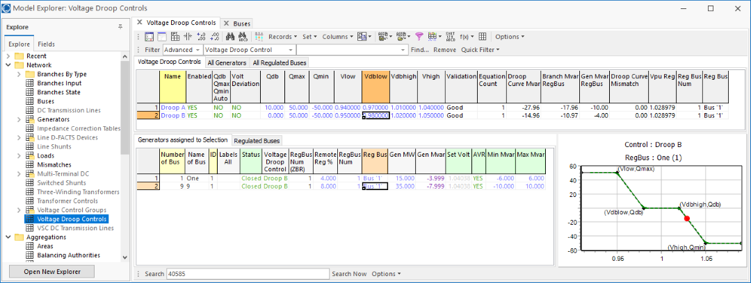
The Voltage droop Control case information display is shown in the following figure.
This display has three tabs which are described below.
Voltage Droop Controls Tab
This is a list of all the VoltageDroopControl objects defined in the case. You can edit the various input parameters for the QV characteristic curve direction on this tabl (Qauot, Vdeviation, Qdb, Qmax, Qmin, Vlow, Vdblow, Vdbhigh, and Vhigh just as you are able to do on the Voltage Droop Control Dialog box. There are also several convenient summary information about the Voltage Droop Control
Validation: This is an indication of whether the VoltageDroopControl has been configured in a valid manner. See Power Flow: Voltage Droop Control with Deadband under the heading "Detection of invalid Voltage Droop Control" for information on how a VoltageDroopControl can be invalid.
Equation Count: This is the number of different regulated buses that are using this VoltageDroopControl. Normally this is only 1, but you can have multiple sets of generators that share the same QV characteristic, but regulate different remote buses.
The remaining fields list next are only populated if EquationCount = 1.
Droop Curve Mvar: This field shows an evaluation of the QV characteristic curve at the present regulated bus voltage.
Branch Mvar Regbus: This is a summation of the Mvar arriving at the regulated bus on arriving branches. Arriving Branches are branches directly connected to the regulated bus which are on paths that connected the generators in the VoltageDroopControl to the regulated bus. As discussed in the Power Flow: Voltage Droop Control with Deadband topic these branches are automatically determined by PowerWorld.
Gen Mvar Regbus: This is a summation of the Mvar for generators that belong to the VoltageDroopControl and are connected to the RegBus directly.
Droop Curve Mismatch: This is showing you the control error mismatch in the VoltageDroopControl. It is equal to Droop Curve Mvar - BranchMvarRegBus - Gen Mvar RegBus. There may be a mismatch in the final power flow solution when generators within the VoltageDroopControl are hitting there Mvar limits.
Reg Bus Num and Reg Bus: Shows the regulated bus number of the generators that belong to this Voltage Droop Control
When you click on a row of Voltage Droop Control list the bottom left portion will show all the generators that have been assigned to that Voltage Droop Control. In addition the bottom right image of the VoltageDroopControl QV Characteristic will be updated. On the image of the QV characteristic, the Red circle denotes the present operating point.
Also in the bottom left there is also a tab for Regulated Buses which will show a list of all the regulated bus for generators assigned. Normally there will only be one bus listed there, but there can be multiple regulated buses. If a Voltage Droop control has generators assigned to it which regulated completely different regulated buses, then within the power flow solution there will be separate treatment as described in the Power Flow: Voltage Droop Control with Deadband topic.
All Generators Tab
This is a list of all the generators in the case and provides you with convenient columns to assign generators to VoltageDroopControl objects. Also as you choose rows in this list the bottom left list of Generators assigned to selection will update showing you generators assigned to the same VoltageDroopControl as the generators selected. In addition the bottom right image of the VoltageDroopControl QV Characteristic will be updated.
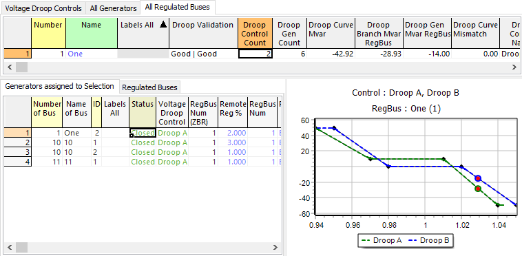
All Regulated Buses Tab
This is a list of all buses that are regulated by generators which belong to a VoltageDroopControl. As you click on the regulated bus the bottom right portion will show the QV characteristic for all VoltageDroopControl objects that contain generators that regulate this bus. It is possible for multiple VoltageDroopControl objects to regulate the same bus as well. In this case the QV characteristic will show two QV characteristics and two Red circles as shown in the image below.